
 Tim Loveless | Principal Solutions Architect
Adjusting System Functionality and Capabilities in LYNX MOSA.ic
I recently set up a demo to showcase how a customer can use subjects, also known as rooms, like containers. What I mean by that is that software...
_______________
At the time of writing, no multicore safety critical software systems exist. That is, no system that utilizes a multi-core processor to execute multiple applications in parallel has been certified for flight by the Federal Aviation Administration (FAA) in the US or by the European Union Aviation Safety Agency (EASA). As such, safety critical avionics systems are missing out on the advances in compute performance, power consumption, and miniaturization enjoyed by laptop, smartphone, and internet users worldwide.
Since 2010, the safety-critical software community has directed tremendous effort at the problem. While progress has been made, current approaches are compromised and incomplete; the search for a general and efficient solution is an area of innovation and active research.
Lynx Software Technologies has built and supported real-time operating systems (RTOSes) since 1988. We have witnessed hardware and embedded software technologies evolve and have supported our customers through the design, development, integration, certification, deployment, and support of software systems across mission-critical applications in AVIONICS, INDUSTRIAL, AUTOMOTIVE, UNMANNED SYSTEMS, DEFENSE, SECURE LAPTOPS, CRITICAL INFRASTRUCTURE, and other markets.
Lynx is involved with multiple researchers as well as companies building complex safety-critical avionics systems. We see first-hand that many do not appreciate why multicore processors present such a serious problem to safety. In this article, we are going to explore reasons why multicore processors do, in fact, present a tremendous safety challenge, including the following:
We will begin by defining our terms, introducing the relevant publications such as CAST-32A, and covering what a safety-critical system is. We will discuss why avionics time constraints demand real-time and how integrated modular avionics (IMA) allows consolidation of such systems. We will examine fault containment through robust partitioning and how this was implemented by ARINC 653 RTOSes to allow the consolidation of applications on common avionics computers, saving SWaP. Next, we will look at the evolution of COTS microprocessors and how Dennard Scaling, a corollary of Moore’s Law, led to multicore processors becoming ubiquitous from the mid-2000s. We introduce the memory wall and hierarchical memory systems built into microprocessors to mitigate the processor to memory performance gap. We will describe how multicore processors expose hardware interference channels present in the hierarchical memory system and how those hardware interference channels go unnoticed in PCs and smartphones but are catastrophic for safety-critical systems.
EASA and FAA, the major regulatory bodies in Europe and the US, have known about the multicore safety problem for the last decade. As regulators, they are impartial judges and want to avoid restricting innovation by favoring one approach vs another. However, they have published guidance to nudge the industry in the right direction.
Real-time safety critical systems must be predictable and have precisely known WCET. Unlike PCs and smart phones, which might seem reliable, real-time systems have hard deadlines that must be met (and be proven). Safety-critical real-time systems, in addition, have hard deadlines that must be met or people die. Predictability is the primary problem when running real-time software on multi-core processors. The worst-case execution time (WCET) of real-time tasks must be predictable and tightly bound in order for the system to reliably meet its deadlines.
Various avionics functions have different time constraints. Flight control is the most time critical and must react within 10 – 20 milliseconds. Fuel management, by comparison, is comparatively relaxed at 100 – 200 milliseconds. The FAA sketches the time constraints of avionics functions in Assurance of Multicore Processors in Airborne Systems.
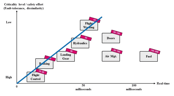
Figure 1 — Correspondence between criticality level and time constraints
In a fly-by-wire flight control system, a computer intervenes between the pilot and aircraft control surfaces. The flight control algorithm depends on precisely timed samples of airspeed, altitude, rate of climb, and so on. If these samples are late, the algorithm can become unstable and the aircraft crashes. The most challenging flight control is found in helicopters.
Electronic flight control systems save weight vs older mechanical systems and can improve safety by avoiding overstress situations such as excessive pitch (nose up) angle, angle-of-attack, and bank angle. Flight control software is typically a loop of a few hundred lines of code tuned to the physics properties of the aircraft. Intelligence can be added to the software to improve comfort by correcting for turbulence and damping yaw to prevent Dutch rolls. For example, the Boeing 787 uses P-Beta control for roll and yaw. Roll-rate (P) is generally controlled by rotating the wheel and yaw, or side-slip angle (ß) by pressing the rudder pedal. Both are required to make a smooth turn, but they are inter-dependent. P-Beta control aims to reduce the dependence so that the wheel gives mostly roll and the pedals mostly sideslip. Reducing unwanted sideslip is good, since it is normally only wanted during crosswind landings. The 787 uses a different control law, called C*u, for the pitch (nose up / down) axis. C*u prioritizes maintaining a fixed speed and adjusts pitch to suit.
The level of rigor required when building aircraft components is determined by Aerospace Recommended Practice (ARP) documents ARP47614 and ARP47545. These standards are used by the FAA and EASA to demonstrate the airworthiness of components from engines and propellers to structures and control systems. ARP4761 prescribes sound safety practices and defines 5 failure condition levels and associated design assurance levels (DALs) ranging from catastrophic (DAL A) to no-effect (DAL E). The most critical systems, such as flight controls whose failure may cause death and loss of the airplane must be built to DAL A; whereas less critical systems, such as telemetry and communications are built to DAL C or DAL D. Specific guidance on how complex software systems must meet each DAL level is provided by the RTCA in DO-178C.
DO-178C6 is the software design assurance process used for avionics software. It prescribes a distinct level of rigor for the software development process for each DAL level to ensure that the software matches its requirements. There are 71 objectives defined to meet DAL A, for example, compared to 26 for DAL D. DO-178C defines a detailed process, following the V-Model, where a project begins by defining its system requirements, then progresses to high level requirements, followed by functional requirements and, finally, to writing source code which is compiled into executable binary code. At every stage, testing is performed to verify that the implementation matches the requirements. Tools are used to verify that every object code path:
This results in a vast library of documentation that dwarfs the source code in both size and cost.
DO-178C is used to build high assurance software for avionics systems. Similar (but less extensive7) standards are used for automotive, medical, industrial, rail, and nuclear systems. DO-178C is followed by Boeing, Airbus, Collins Aerospace (Raytheon) and Thales to write safety critical applications and it is used by a small market of suppliers such as Lynx, Wind River, DDCI and SYSGO who sell commercial safety-critical real-time operating systems (RTOSes).
The first electronic systems in aircraft were separate metal boxes called line-replaceable units (LRUs). These independently removable boxes contained their own electrical connectors, power supplies, and latterly, embedded computers. Cockpits and avionics bays of aircraft from the 1990’s were a mass of pluggable metal boxes crammed together to create the avionics suite. Consider a radar altimeter, it has a sensor unit mounted outside the fuselage connected to an LRU in the cockpit with an indicator for the pilot. There will be a pair of cockpit LRUs, since the co-pilot needs an indicator too, and possibly a pair of radar sensors for redundancy. Add other systems such as barometric altimeters, air and ground-speed sensors, artificial horizons, angle-of-attack sensors, auto pilot, instrument landing, and navigation systems and it is clear the aircraft is crammed with LRUs. This architecture of avionics is called a federated system. In federated avionics systems each LRU is built and sold independently from suppliers such as Collins Aerospace, Honeywell, Thales Avionics and GE Aviation.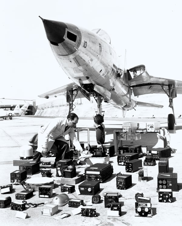
Figure 2 — LRUs under a F105 Thunderchief
As the number of LRUs in aircraft grew, the space required for all the metal boxes as well as their weight and electrical power requirements became excessive. From the 2000’s, Honeywell led a new avionics architecture with the aim of consolidating federated systems to reduce their space weight and power (SWaP). Integrated Modular Avionics (IMA) is a real-time computer network designed so that LRUs can be implemented as software modules running on shared computing platforms. Modern avionics systems are complex interconnected real-time networks of computer systems carefully designed and synchronized so that every component meets its deadline.
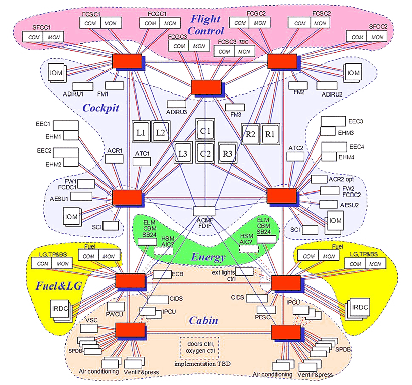
Figure 3 — The open IMA network on the Airbus A380
For example, Figure 3 shows the avionics architecture of the Airbus A380. Every white box is a computer, grey boxes are displays, red and blue shows ethernet links and gateways.
RTCA DO-2978 provides certification guidance specific to Integrated Modular Avionics systems. It is concerned with how separately certified IMA components can be integrated together so that their certification is reused and preserved in the integrated end system. Aeronautical Radio, Incorporated, (ARINC) is the maintainer of the physical ARINC standards for LRUs (size, mounting hardware, electrical connectors), and more recently, the IMA software connectivity standards too. ARINC 6539 defines the software interface used to allow software modules to share common computers in IMA systems. The natural “air gap” fault containment of federated avionics systems is lost with the move to shared computers so the most critical specification of ARINC 653 is its definition of robust partitioning.
Robust partitioning is necessary to ensure separation between applications sharing an IMA computer. Faults must be contained and prevented from propagating from one partition to another. A robustly partitioned system means that applications can be verified, validated and safety certified independently from one another, and that applications of mixed criticality (DAL) levels can be hosted together on the same IMA platform. These are crucial elements of IMA. Validating non-partitioned applications is expensive because they are larger, and unattractive because they are less re-usable. Without robust partitioning the whole point of IMA, equivalent fault containment to federated systems, is lost.
The reference study on robust partitioning is Partitioning in Avionics Architectures: Requirements, Mechanisms, and Assurance10 by John Rushby for the FAA in 1999. Rushby defined the Gold Standard for Partitioning as:
“A partitioned system should provide fault containment equivalent to an idealized system in which each partition is allocated an independent processor and associated peripheral and all inter-partition communications are carried on dedicated lines...”
But, Rushby knew that no such idealized system existed to measure your partitioned system against. So, to help building testing and evaluating real-world software he introduced this stronger property, named the Alternative Gold Standard:
“The behavior and performance of software in one partition must be unaffected by software in other partitions”
There are two aspects to robust partitioning, robust time partitioning and robust space partitioning. Space partitioning is easier, a partition must be prevented from accessing the software or data of other partitions. Time partitioning requires that the responsiveness of shared resources in one partition cannot be affected by software in another partition. For example, the CPU performance and memory bandwidth of one partition cannot be impacted by another. These partitioning tasks are already being done by RTOSes, their processes are naturally similar to ARINC partitions. An RTOS process is space partitioned in its own private MMU-enforced region of memory and an RTOS process is time partitioned since its access to the CPU is controlled by the RTOS scheduler.
Led by Wind River, RTOS companies extended their operating systems to support ARINC 653. A simplified round-robin scheduler replaced the RTOS priority pre-emptive scheduler. In a round-robin scheduler (also called an ARINC scheduler, or a time partition scheduler) all partitions are allocated slots in a major frame. Slots may be repeated and of varying lengths, but the major frame is fixed and is repeatedly executed forever. This round-robin schedule is not as efficient as the RTOS’s usual scheduler, but it guarantees periodic fixed-length execution slots for all partitions in the system. The WCET of applications is carefully measured and they are assigned to partitions and allocated sufficient time to meet their deadlines. Large systems, with dozens of computers, such as the A380 (Fig 3) can be constructed and configured with synchronized time slots between computers so that sensor data is only sent from one computer when the recipient computer is ready to receive it. In this way large IMA systems can be built integrating up to 200 avionics applications onto dozens of computers realizing the goal of space, weight, and power (SWaP) savings promised by IMA.
Embedded and real-time systems have long used commercial-off-the-shelf (COTS) microprocessors. Soaring semiconductor fabrication costs are affordable to only a handful of large companies worldwide like Samsung, Intel, and Taiwan Semiconductor. They take advantage of Dennard scaling11, a corollary of Moore’s law, to manufacture the most desirable chips. Dennard scaling says every time transistor density doubles, the circuit becomes 40% faster and power consumption (with twice the number of transistors) stays the same. This has been a powerful driver of industry consolidation, leading to Arm and Intel microprocessors dominating today.
Embedded real-time systems have benefited greatly from advances in COTs microprocessors and avionics systems are no exception. However, aviation is low volume - the number of avionics systems sold is tiny compared with the number of PCs or smartphones - so while avionics benefits from advances in COTS microprocessors, it has no influence over them.
Dennard scaling works because smaller transistors consume less power and can so be clocked faster with the same cooling (TDP). In addition, smaller circuits reduce propagation delays further improving speed. Around 2006 current leakage from ever smaller transistors running at higher speeds caused the breakdown of Dennard scaling. Semiconductor manufacturers could continue to improve the size of transistors with every generation, but not the clock frequencies – which levelled off at around 3GHz. With transistor counts continuing to double every 2 years, manufacturers turned to multi-core processors to continue offering higher performance to users.
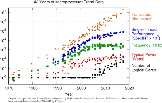
Figure 4 — Microprocessor trend data since 1970
Everything changed with multicore processors, although superficially just “better and faster” than single core processors, multicore processors are vastly more complicated under the hood. They genuinely do run multiple processes in parallel – instead of using rapid scheduling to appear to do so – as single-core processors do. Multicore processors work beautifully for desktop PCs and smartphones, but as we shall see, they create a gigantic headache for safety-critical avionics systems.
Multicore processors are built for SMP (symmetric multi-processing) operating systems. SMP OSes are aware of all cores and schedule processes across the cores in order to balance the load. This is the approach used by Windows, Linux, iOS, and Android to use the computing power of MCPs.
Multicore processors cause a separate problem for real-time systems in the area of scheduling. The entire RTOS industry was built on the foundational scheduling work12 of Lui Sha. Sha proved that the rate monotonic scheduling (RMS) algorithm is both able to schedule a set of periodic tasks so that they all meet their deadline and that it does so optimally. Sha showed this holds if the processor utilization of the system is below 69%. The 69% worst-case threshold of schedulability improves to approximately 88% with large task sets if the period of the longest task is within 100 times the shortest one. Sha’s work means that multitasking real-time systems can be guaranteed to hit their deadlines as long as sufficient CPU headroom is allowed for. The big catch is that this scheduling work is based on single core processors. There is no real-time SMP scheduling algorithm known for scheduling tasks on multicore processors. SMP OSs like Windows, Linux, iOS and Android use priorities and heuristics to do a good job, but they cannot guarantee to meet task deadlines. In computer science multiprocessor scheduling is a load balancing problem known to be NP-complete. That is, the task of finding a schedule of N tasks on M processor cores such that all tasks meet their deadline has no efficient algorithm other than brute force. This means that the term SMP RTOS is an oxymoron – there is no known way to build an RTOS with SMP scheduling. Instead multicore RTOSes use scheduler compromises like core affinity and bound multiprocessing (BMP).
The memory wall13 is a side effect of processor performance outpacing memory performance. It says that as the gap between processor and memory performance grows computers will become memory bound and that no improvement of cache size or hit rate will help. This strong statement is justified because despite processor performance and memory performance both growing exponentially, processor performance has the higher exponent and the difference between diverging exponentials also grows exponentially.
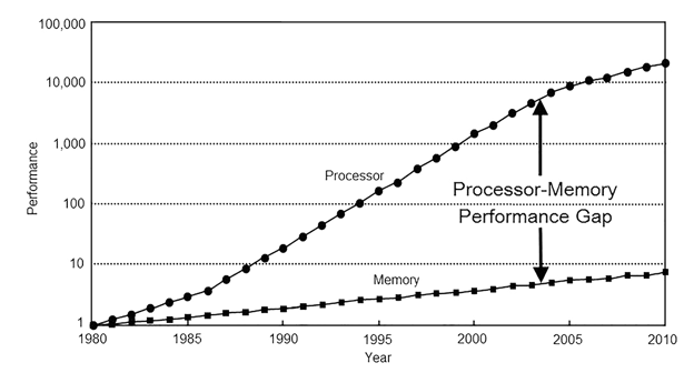
Figure 5 — The growing processor-memory performance gap (from Computer Architecture: A Quantitative Approach by John L. Hennessy, David A Patterson, Andrea C. Arpaci-Dusseau)
In the last 40 years we have seen processor performance grow at 80%14 per year and memory performance grow at a paltry 7%15. The processor-memory performance gap has slowed in the last 10 years, but the memory wall is still important. In order to feed hungry processors and bridge the performance gap, semiconductor manufacturers have built complex multi-layered cache structures. In normal operation they do an incredibly good job of keeping the right instructions and data in cache and of predicting what to keep there to maximize performance.
But there is no way around it, sometimes your program will jump to instructions, or need to read data, that are outside cache and you will be forced to take a cache miss. For example, the Intel Core i7-1065G7 (Ice Lake) processor launched in Q3 2019 is a quad core chip with 3 cache levels. It runs at 1.3Ghz with 3.9Ghz turbo mode. At 1.3Ghz each instruction cycle is 0.77 nsecs†, whereas a RAM access takes 129 nsecs16, about 160 times as long. Building a coherent multi-core memory system with multi-layer caches is incredibly complex. The system has to keep track of whose cache has the latest version of shared data, and to make sure that it is written back to main memory (or is snooped directly into a different cache) quickly if another core reads the same data. The coherent memory system has to be as fast as possible since overall performance depends on it and it must be as efficient to build as possible to keep the microprocessor affordable. The internals of the hierarchical memory system are competitively sensitive and will be closely guarded intellectual property of Arm or Intel.
It is easy to write a memory-hog application that abuses the shared memory system. An application that writes bytes into a giant array, with a gap of 1 cache line (64-bytes) between each write will quickly evict every cache line and fill them with its own data. Such a noisy neighbor application exposes a cache’s worst case scenario, and if that cache is shared between cores, it is an interference channel that breaks robust partitioning. Specifically, it violates robust time partitioning by forcing the victim to suffer many extra cache misses. If a cache miss takes 160 times as long, the performance impact is dramatic. Interference channels are the focus of much multi-core research. The last level cache (LLC)—level-3 on most Intel processors—is closest to RAM and usually shared between all cores. LLC is an obvious and significant interference point, but crucially it is not the only interference point. Interference can occur anywhere that hardware resources are shared. The entire hierarchical memory system is shared between all cores, so interference is possible in many places. For example, if a pair of L2 cache misses from different cores happen on the same clock cycle, the arbiter that decides which L2 miss to satisfy first may not be fair. Another example, each DRAM DIMM is organized into between 8 and 16 banks. DRAM accesses can be made in parallel, but only if they are for different banks. This kind of detail and subtlety exists throughout the hierarchical memory system and is often undocumented because it forms part of Intel or Arm’s intellectual property. It was not expected that microprocessor users would need to predict when their code would stall due to a cache miss or other interference source. Microprocessors are built on the assumption that high performance on average for a normal software workload is good enough. They assume that small stalls are acceptable as long as they are rare and overall performance is high. This is true for practically all use-cases, but not for safety-critical real-time unfortunately.
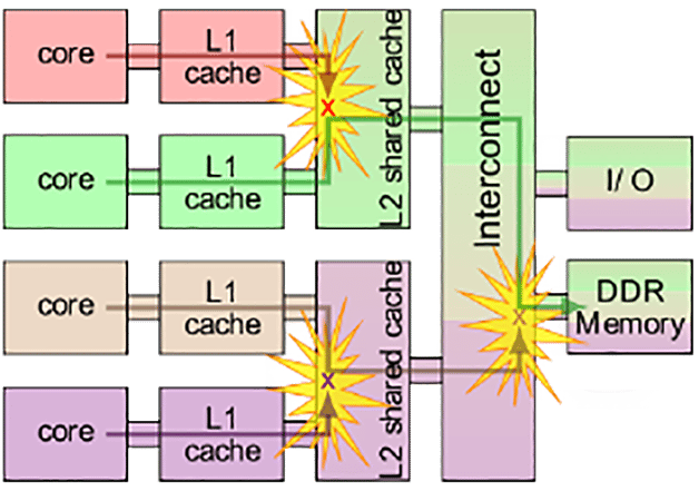
Figure 6 — Simplified typical multicore system architecture
The problem with this assumption is that core stalls due to interference are not only caused by noisy neighbors. Badly behaved applications cause more interference, that is easy to see, but interference could be happening all the time, just going un-noticed. Even if interference is exceedingly rare, the FAA says in CAST-32A, that it must be identified, measured, and verified not to exceed budget.
Under the hood at the microarchitectural and cpu-clock level, co-running applications on a multi-core processor will inevitably run with slightly different timing from one run to the next. With the cpu core clocked at 1Ghz and analog sensors and actuators subject to vagaries in temperature, wear and manufacturing tolerances, it is inevitable that tiny variations in the timing of external i/o events will cause one core to access a memory address a few cycles earlier, and potentially evict a different cache line, with further timing consequences later. That is, the interleaving of memory accesses from the instruction streams of co-running applications will cause the internal state of the hierarchical memory system to be unpredictable. This is important because it means that interference can be caused by all applications, not just noisy neighbors. In rare situations, the sequence of memory accesses caused by the interleaved instruction streams of co-running applications may over-step a cache size, buffer structure or bandwidth boundary, for example, and hit an edge case that briefly causes interference. Such interference could cause an application to miss its deadline and trigger a failure in the real-time system. As defined in ARP4761, DAL A systems must be built to the level of rigor such that the probability of failure is below 10−9 per flight hour. That is, 1 chance in 1,000,000,000 per hour (equivalent to 1 failure in 140,000 years). For this reason, even if it is rare, interference must be addressed and managed if multi-core processors are to be used in safety-critical systems.
Interference is observed as jitter in the execution-time of repetitive tasks. Real-time tasks run in a loop repeating the same time-critical function constrained by their deadline. Ideally the execution-time of the task from one run to the next should be identical. In practice, even on single-core processors, small variations are observed. As long as the execution-time distribution is still tightly constrained, the worst-case execution-time (WCET) can be determined and appropriate task deadlines assigned to achieve better than one failure per 1,000,000,000 hours.
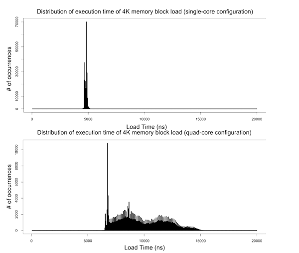
Figure 7 — Execution time distribution: single core vs multicore
The problem with multicore processors is that hardware interference channels cause the execution-time distribution to spread. Instead of a tight peak, the distribution is wide with a long tail. With such a distribution it is difficult to build the confidence interval required to know where to set your deadline to meet one failure per 1,000,000,000 hours. Long tail distributions like these, are caused by unpredictable systems. With such systems it is difficult to know if you have found all the nasty outliers and really captured your WCET. Such unpredictable performance may require a deadline so conservative that it defeats the benefit of the multicore processor.
It is tempting to think that if hardware interference is modest, maybe it can be ignored. Afterall, millions of PCs and smartphones seem to run reliably and routinely deal with time sensitive tasks such as voip calls and CDMA frequency-hopping. Unfortunately, hardware interference is significant and dramatic slowdown of one core has been shown when adversarial software is run on the other cores. Bechtel and Yun achieved a factor of 340 times slowdown17 on a Raspberry Pi 3, which runs a quad core Arm Cortex-A53 processor. In other work18, Yun saw less dramatic, but still catastrophic interference of 8 times slowdown on Intel Nehalem and 29 times slowdown on Arm Cortex-A15 even when cache partitioning was used. Such dramatic results illustrate the gravity of the problem. These are worst case examples generated with artificially adversarial benchmarks, but they prove the presence and seriousness of hardware interference channels.
Safety-critical real-time systems have such a miniscule acceptable failure rate that they are sensitive to even modest levels of interference. It seems likely, since they are built with common design goals, that the majority of mainstream multicore processors exhibit hardware interference. It is also probable that even well-behaved software will trigger interference occasionally. The challenge of the multicore safety problem is to robustly prevent such interference without drastically reducing the MCP's performance.
For the last 30 years computer technology has advanced at a tremendous pace. All kinds of discoveries have advanced semiconductor fabrication technology and pushed computer architecture design resulting in the incredible range of small powerful cheap and efficient microprocessors we see around us today. Multicore processors were an engineering solution to a problem caused by reduced transistor size. Similarly, multilevel cache memory hierarchies were built to address the memory wall performance bottleneck. Over the same time period the aviation safety community developed a rigorous safety assurance process that delivers incredible reliability for all aircraft systems, be they engines, propellers, structures or control systems. In pursuit of efficiency, autonomy and safety, aircraft systems first moved to electronic systems, and later to integrated modular avionics (IMA) systems. Unfortunately, COTS microprocessors are built for high performance on average rather than minimizing WCET. Such processors exhibit unacceptably high interference between cores to host multiple applications according to the rigorous safety assurance process required for avionics software. In 2010 this unfortunate collision of paths led to an impasse, the multicore safety problem, in the safety-critical aviation software community. The search for a general and efficient solution remains an open research topic at the time of writing.
Multicore safety is an area of expertise and active innovation for Lynx Software Technologies. Multicore designs should be approached with caution and careful planning to understand the complexity and minimize risks. Our experience is that there are large pitfalls and no easy solutions. We are engaged in several multicore avionics design and research projects and would be delighted to discuss multicore safety and partitioning strategies for your next project.

† Approximately. Intel Core i7-1065G7 is a superscalar processor, it achieves more than 1 instruction per clock.
I recently set up a demo to showcase how a customer can use subjects, also known as rooms, like containers. What I mean by that is that software...
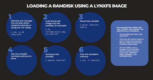
Based on several customers inquiries the purpose of this blog is to outline how to Allocate memory to a RAM disk Mount and unmount a RAM disk ...

Not many companies have the expertise to build software to meet the DO-178C (Aviation), IEC61508 (Industrial), or ISO26262 (Automotive) safety...