
 Lynx Software Technologies
Adjusting System Functionality and Capabilities in LYNX MOSA.ic
I recently set up a demo to showcase how a customer can use subjects, also known as rooms, like containers. What I mean by that is that software...
_______________
Industry 4.0? Edge computing? Call it what you will, the fact remains that our industry moves slowly. Obstacles must be overcome before we can claim that edge computing has evolved from theories and experiments to true industrial deployment. The resolution of the mismatched and (potentially insecure) interface between the worlds of Informational and Operational Technologies (IT and OT) is key to the application of edge computing on a wider scale.
Consolidating multiple systems onto single multicore processors can reduce cost, power, and footprint, but it can also create real-time performance challenges due to sharing of resources. There is also a desire to lower costs and improve flexibility by transferring traditional industrial network functionality from hardware to software implementations.
There is, however, an opportunity to address each of these issues by leveraging separation kernel hypervisors to enable the secure and safe sharing of multicore processors, and by redefining the second layer of the automation pyramid—the supervisory layer—to be software driven.
Referencing the real-world example of a car manufacturer dramatically improving their quality-control processes, we will examine the results from a testbed created in association with a number of pioneering European companies that can deploy data analytics workloads, communication protocol translation, and control workloads on the same platform without compromising performance. We will also discuss specific performance measurements for a Virtual PLC architecture which validates that this is a feasible path for the industry. Finally, we will demonstrate that the combination of these technologies can help shift Industry 4.0 and edge computing from the experimental to the everyday.
In the industrial automation vertical, there is broad agreement that the deployment of modern computing resources with cloud native models of software lifecycle management will become ever more pervasive. Placing virtualized computing resources nearer to where multiple streams of data are created is clearly beneficial, but system latency, privacy, cost, and resiliency challenges remain that a pure cloud computing approach cannot address.
Cisco Systems initiated a paradigm shift around 2010, looking to address those issues under the label “fog computing” – a line of thinking that has progressively morphed into what is now known as “edge computing”. Don’t be dazzled by the buzzwords – edge computing is simply computing that is done at or near the source of the data, instead of relying on the cloud at one of a dozen data centers to do all the work.
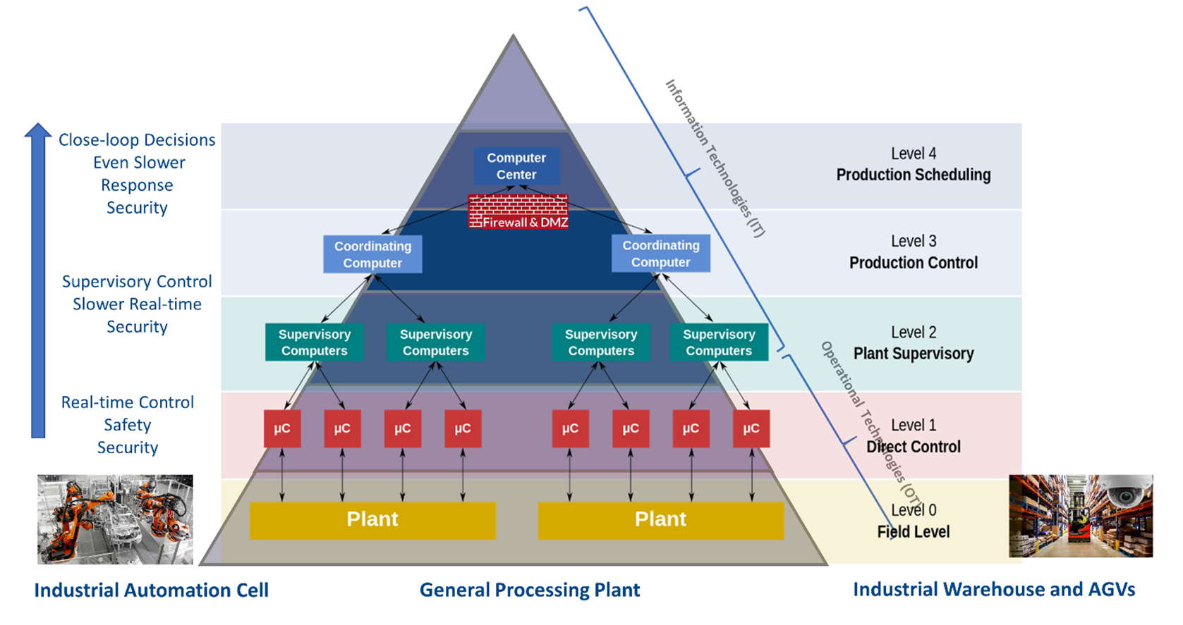
Figure 1: The industrial pyramid: A hierarchical control system
The industrial (or automation) pyramid classifies the different IT and OT layers of industrial automated production plants. Every layer (or level) has its own tasks and infrastructure. Although the principle is generally consistent, the structure and its representation can vary, as can the number of layers depicted. One representation of the industrial pyramid is shown in Figure 1. Level 0 (field level) is closest to the devices and sensors, whereas Level 4 (production scheduling) is the furthest from the manufacturing floor.
Characteristics of devices and systems vary accordingly. For example, systems at level 0 are usually ruggedized, fan-less designs with limited CPU and memory. Safety, security, and tight real-time control loops are paramount – clear examples of where edge computing is appropriate. Level 4 systems, on the other hand, do not operate in harsh environments, are usually associated with lot more computational capabilities, have less demanding real-time requirements, and hence have no need to operate near the data source.
Level 2 (plant supervisory level) represents the median of control, determinism and computation and is usually the focus of OT and IT convergence. It is easy to forget in this world of neat diagrams and newly-coined phrases that such convergence represents an awkward coming together of two traditionally distinct worlds. For example, traditional OT includes built-in security by virtue of its isolation, whereas IT security is focused on protecting enterprise assets. Connecting them exposes the security of both systems, simply because in each case it implies the provision of a potential means of access which they weren’t designed for.
The net result of such challenges is that system builders and administrators typically don’t mix IT technologies (that work in level 3 or level 4) with OT workflows (level 0 through to level 2). Convergence and cross-pollination of the respective efficiencies of the resulting OT and IT “silos” is therefore limited.
Edge computing exists to accommodate characteristics and deliver requirements that cloud native paradigms cannot cater for such as those required in the lower, OT focused levels of the industrial pyramid. These include:
The “mission critical edge” concept is born out of the incorporation of requirements typical of embedded computing (security, real-time and safe, deterministic behaviors), into modern networked, virtualized, containerized lifecycle management and data and intelligence rich computing. It addresses the challenges of the IT/OT interface head on, providing support for essential yet fragmented legacy systems through their secure consolidation and orchestration, and encouraging their enrichment with the fruits of data analytics and artificial intelligence (AI).
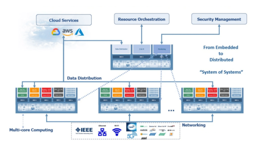
Figure 2: Addressing the challenge of the OT/IT interface with an integrated "system of systems"
Consider the broad architecture illustrated in Figure 2. It represents the vision of a distributed and interconnected, mixed criticality capable, virtualized multicore computing nodes (system of systems) with support for yesterday’s, today’s, and tomorrow’s technologies.
Such an architecture would provide:
With this vision in mind, Lynx has partnered with EXOR, CODESYS and Next Stel to build an industrial testbed . EXOR is both a hardware original equipment manufacturer, and an edge software provider with specialization in data ingestion and analytics frameworks. CODESYS offers virtual PLC eco-systems running on Debian Linux, or as self-contained bare-metal solution. And Next Stel is a Systems Integrator with considerable experience in design and deployment of industrial control systems in Italy and neighboring countries.
The testbed uses an EXOR eCC3800e industrial grade compute element running a 4-core (8-thread) Intel CPU with 16GB of RAM (Figure 3), hosting Lynx’s LynxSecure® hypervisor.
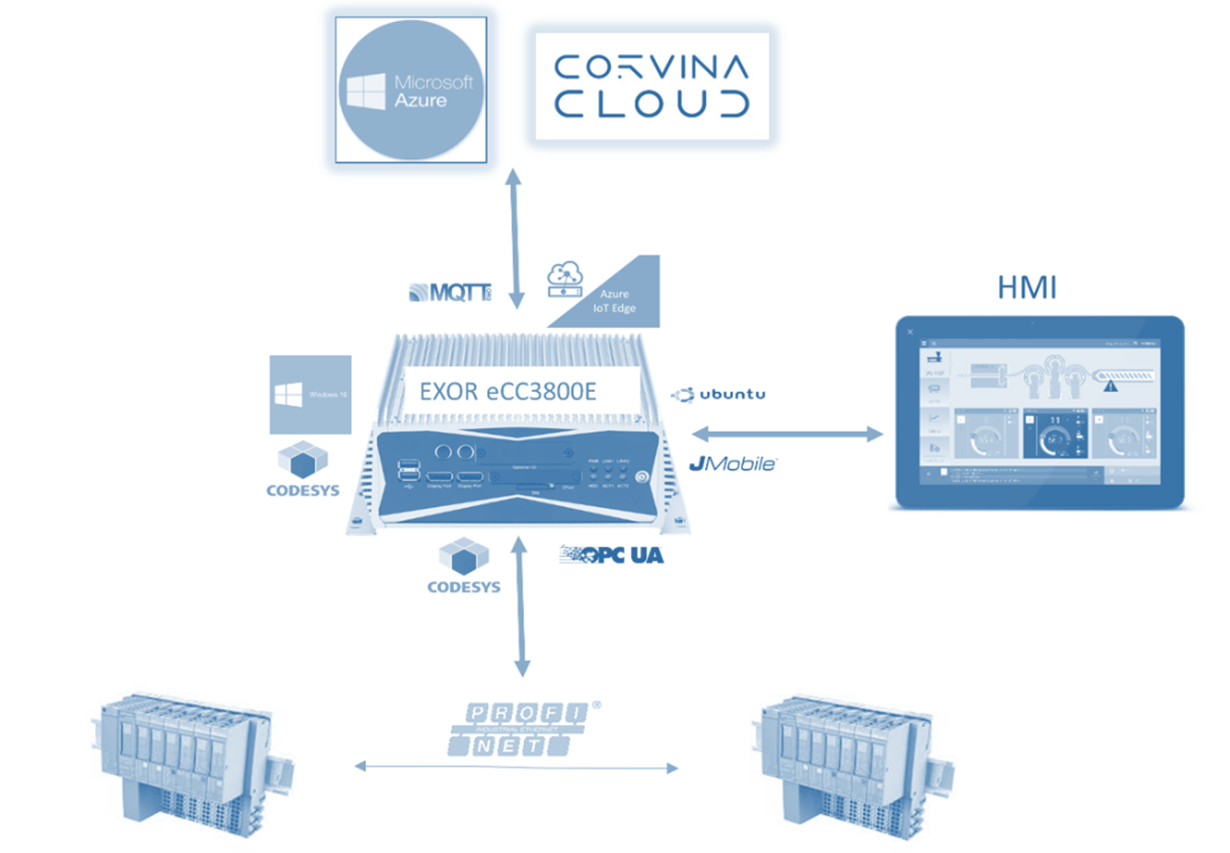
Figure 3: The industrial testbed
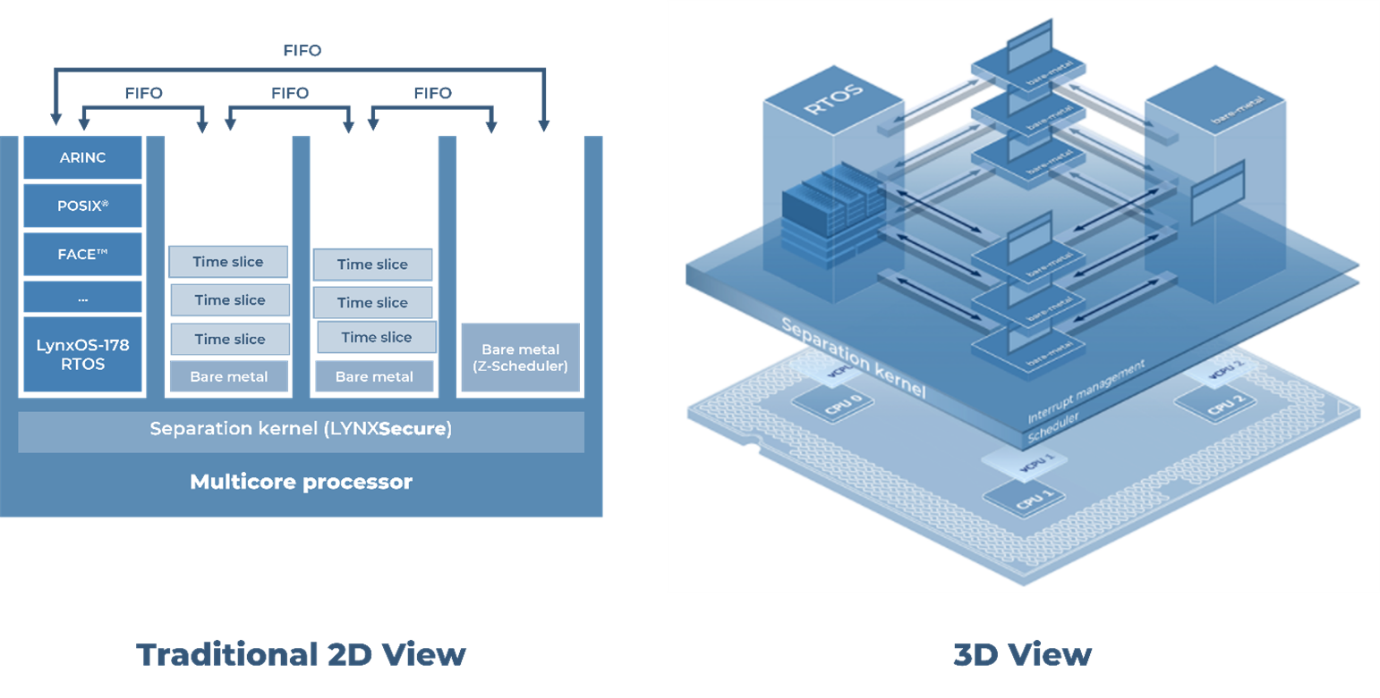
As illustrated in Figure 4, LynxSecure is configured with four guests (or subjects, as they are known in LynxSecure parlance).
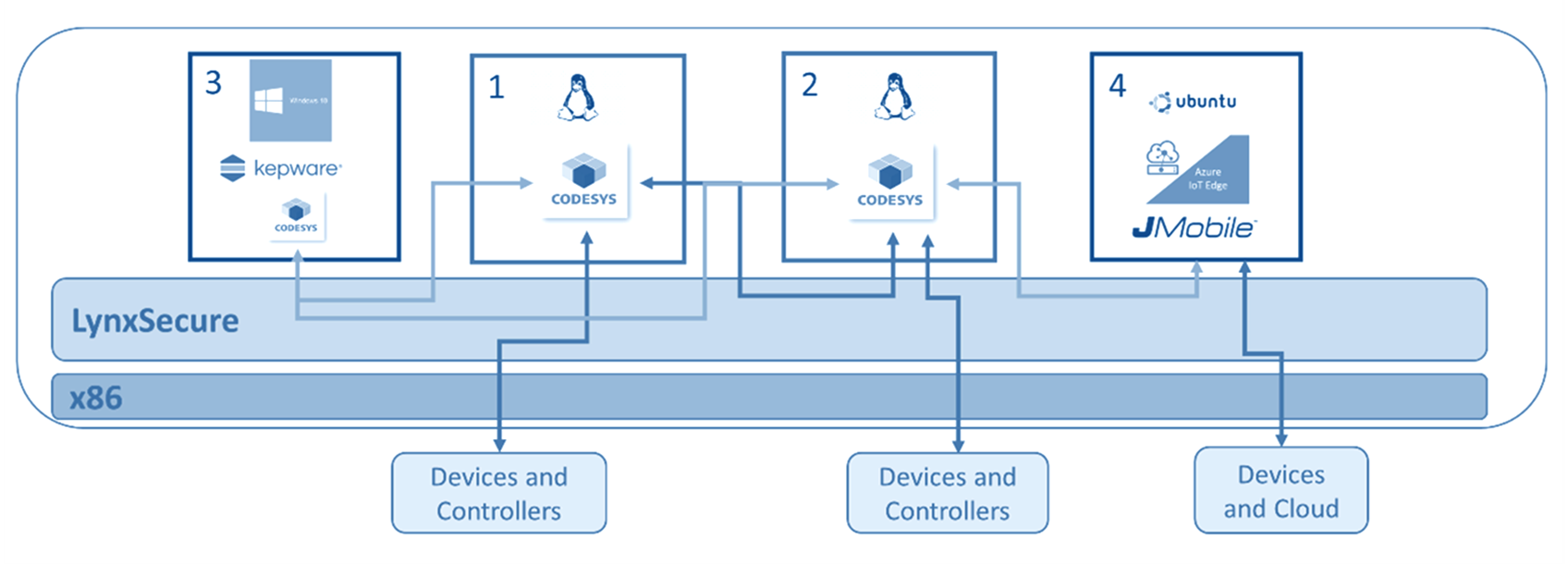
Figure 4: The LynxSecure configuration
There are two Debian Linux subjects with RT preempt patches (labelled “1” and “2” in the diagram). A CODESYS run-time runs on each, connecting the industrial PC to Siemens remote I/O devices over a ProfiNET (industrial ethernet) link. The use of two subjects facilitates the instantiation of a hierarchical control loop, with one CODESYS run time running a much tighter control loop (of 250 us) and the other CODESYS run time operating a slightly slower control loop (2 ms).
The CODESYS run times are managed via a CODESYS IDE running on a Windows subject (labelled “3”).
JMobile and Azure IoT Edge run-times run on an Ubuntu subject (labelled “4”). JMobile, an EXOR software application, is used to ingest and filter data transferred from the Siemens remote I/O devices via the CODESYS runtimes. In addition to managing the incoming data, JMobile can also provide an HMI for a cell operator.
Data from JMobile is routed towards EXOR's Corvina Cloud and to Azure IoT Hub. JMobile communicates directly with Corvina Cloud using OPC-UA, and forwards data to the Azure IoT hub via the Azure IoT run-time using MQTT protocol.
For such a such configuration to be a practical proposition, its performance must be within the demanding parameters of the OT-focused levels of the industrial pyramid. That would depend largely on the performance capabilities of the virtualized applications.
Because a typical industrial control is based on a cyclic control, a control system must guarantee that the all the computations at the two end points of the control loop, and all the communications between these points required in every control cycle are completed before the beginning of the next cycle. Figure 5 illustrates a simple example, with a Master Controller and an I/O Module communicating through a time-sensitive Field Bus, such as ProfiNet and EtherCat.
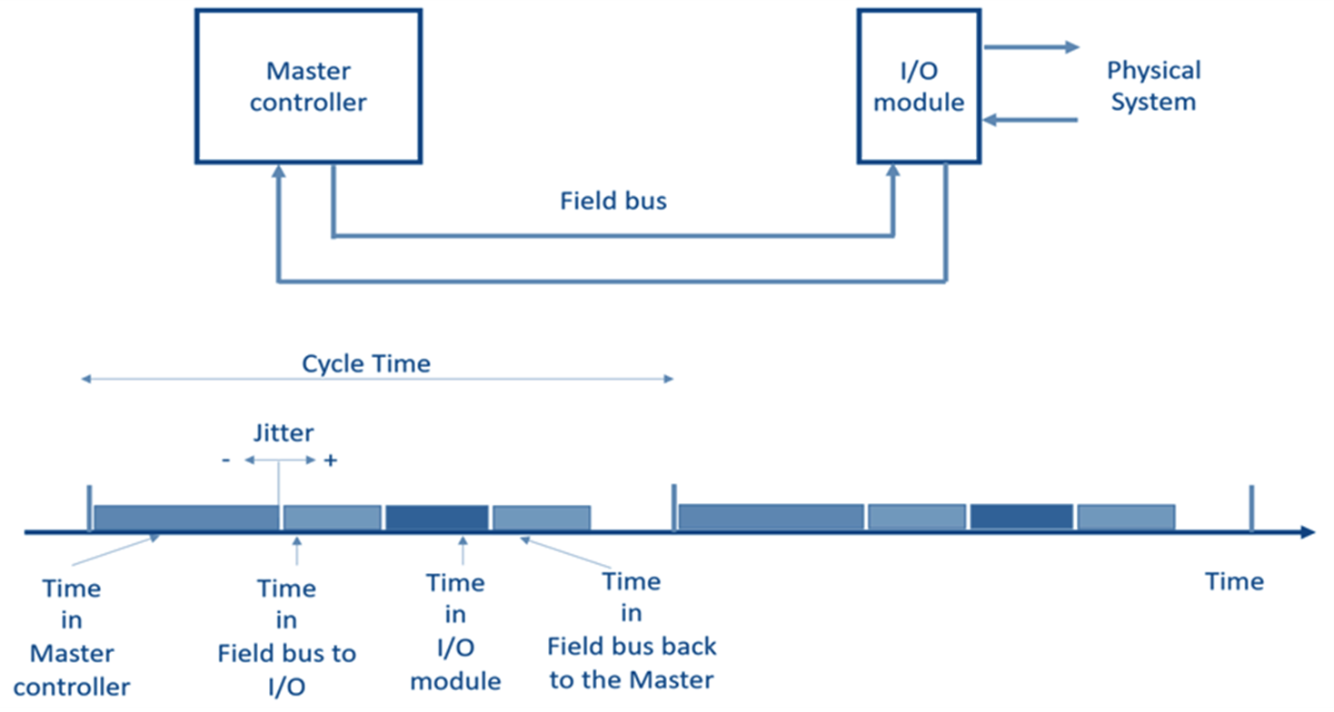
Figure 5: A simple control system
As illustrated, this interval will typically not be constant for a number of reasons, but will vary from cycle to cycle. The variability, known as Jitter, may assume positive or negative vales, and is acceptable as long as it will not cause the failure to complete all the activities required within a cycle before the beginning of the next cycle. Typically, the maximum jitter is acceptable only if it is smaller than 1/2 a cycle time.
Preliminary tests were carried out to measure the performance of real-time communications between the CODESYS run-time and the external Siemens remote I/O device. A Profinet bus tap was inserted between the CODESYS ladder logic application and the Siemens remote I/O device. The collected network traffic was analyzed by a data collection system to measure the latency and jitter values associated with the communication between the CODESYS run-time and the external I/O device.
Three sets of measurements were taken - with CODESYS running on bare-metal hardware, with
CODESYS running on LynxSecure, and finally with CODESYS running on top of LynxSecure with interfering workloads. In all 3 cases, CODESYS ladder logic application was driven at a cycle time of 250 us.
As Figure 6 illustrates, there was very little deterioration in real-time performance when the CODESYS application is migrated from bare-metal to LynxSecure environment, and no appreciable deterioration in real-time performance of the CODESYS application running on top of LynxSecure with or without the presence of interfering workloads.
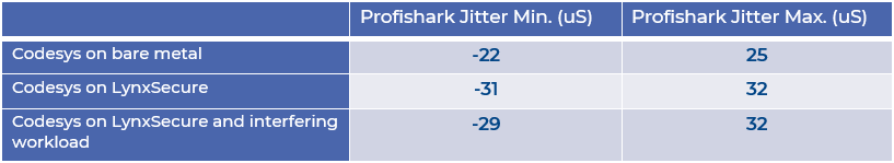
Figure 6: Preliminary test results
In light of these encouraging results, more thorough performance testing was carried out by Next Stel Solutions to provide an evaluation of how good the selected architecture is at handling real-time network traffic.
In an extension to the preliminary tests, two alternative configurations were used in order to validate the solution with two widely used industrial fieldbuses: EtherCAT and ProfiNET, illustrated in Figure 7 and Figure 9 respectively.
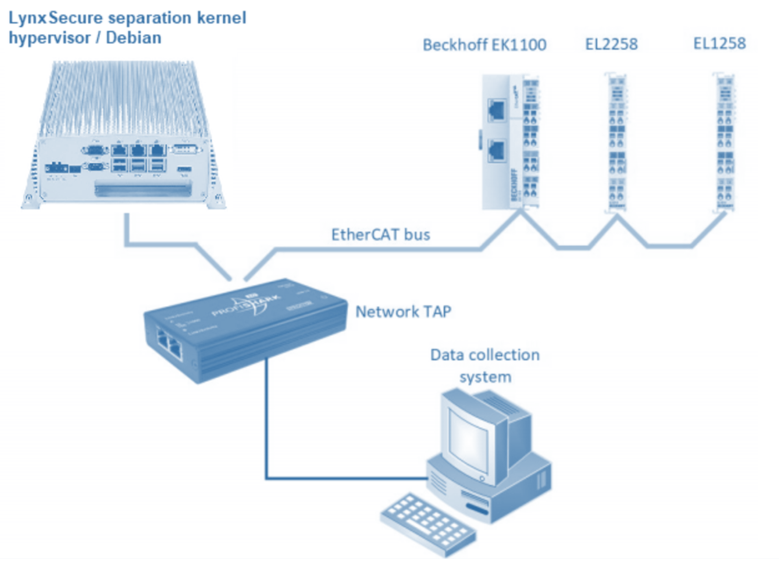
Figure 7: Hardware setup for EtherCAT
In an extensive analysis giving due consideration to jitter, scheduling latency and network stack latency, the study concluded that that the LynxSecure hypervisor was effectively isolating critical real-time activities from other activities hosted on the same system, while adding up to 50 us to the jitter observed in the equivalent set up, but without virtualization (Figure 8).
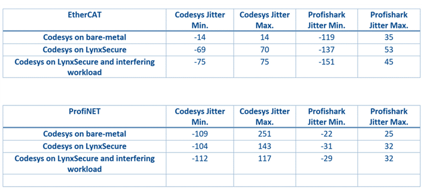
Figure 8: Results overview
It was also observed that these results were obtained under full virtualization and without any performance optimization, and suggested that even better results could be obtained by using a Para-virtualized Linux OS with RT patches, and applying other potential performance optimizations.
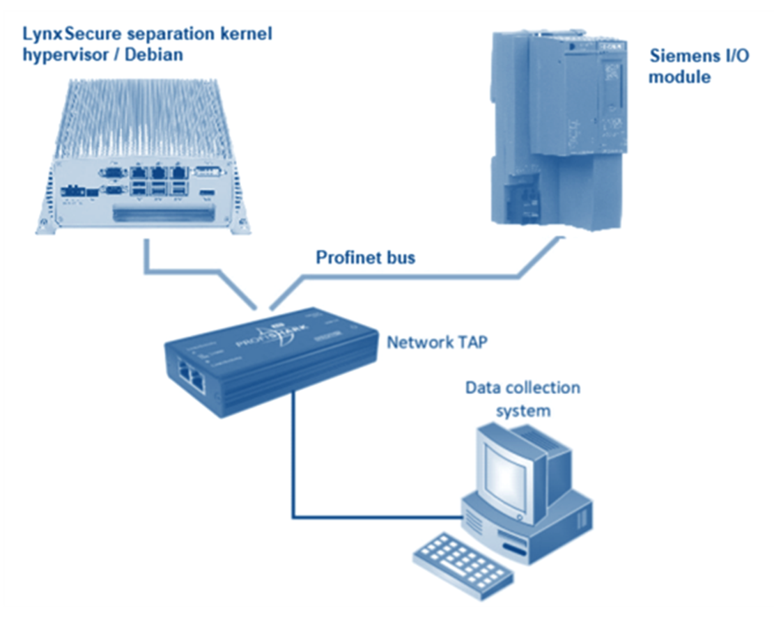
Figure 9: Hardware setup for ProfiNET
It was concluded that the minimum cycle time that could be handled by this solution would be 250 microseconds both for EtherCAT and ProfiNET. Even faster cycle times are likely to be possible should para-virtualization and/or a different RTOS than Debian RT be leveraged.
It is clear from these results that the proposed solution can address each of the primary challenges presented by the IT/OT interface, while maintaining the real-time, deterministic performance demanded by OT applications.
The flexibility provided through virtualization makes the concept sufficiently flexible to address the issue of heterogeneous hardware, while offering support to legacy systems and innovative data analytics on the same platform. The security issues created by the marriage of the disparate IT and OT worlds are addressed by the domain separation inherent in the solution, and least-privilege principles used as the basis for LynxSecure’s design. And those same principles provide the platform to ensure that data privacy can maintained.
Figure 10 shows how the infrastructure would look when the mission critical edge is deployed, embedded into the operational technologies area of the factory. There are a distributed set of nodes, some quite close to the plant, some far away. Effectively this is like a distributed datacenter, yet contains a far more heterogeneous, interconnected virtualized set of computing resource which can host the applications where needed and when needed. These will be deployed in the form of virtual machines and containers orchestrated from the cloud or locally.
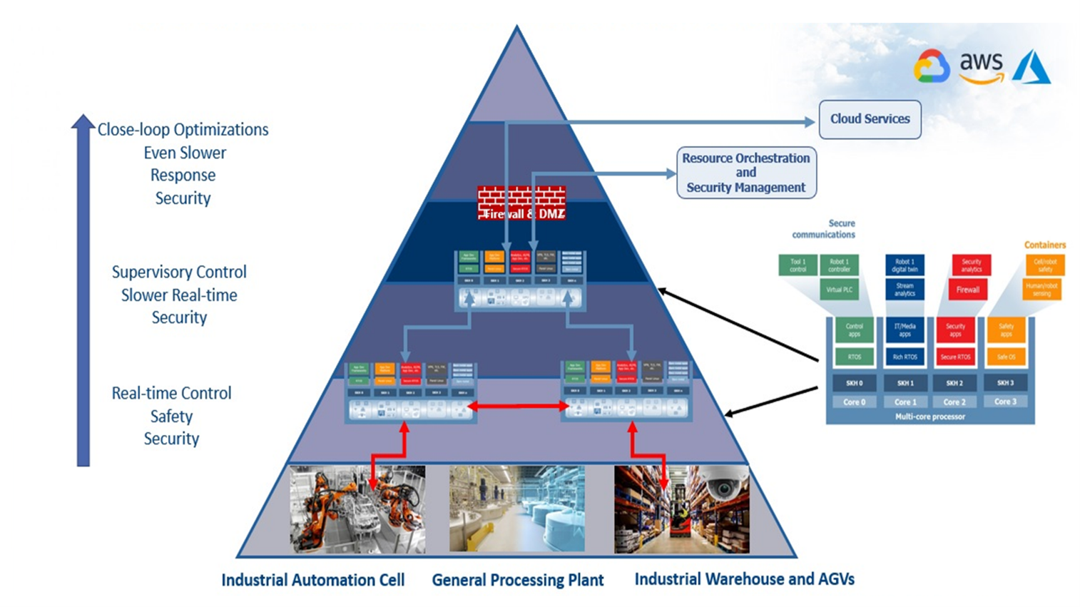
Figure 10: The industrial pyramid and the mission critical edge
Now consider this principle in the context of a specific use case at an Audi manufacturing plant, more specifically for the Audi A3. Audi worked with Intel and Nebbiolo on a proof of concept (POC) experiment focused on improving the quality-control process for the welds on its vehicles. The POC took place at Audi’s factory in Neckarsulm, Germany, one the company’s two principal assembly plants The Neckarsulm plant has 2,500 autonomous robots on its production line. Each robot is equipped with a tool of some kind, from glue guns to screwdrivers, and performs a specific task required to assemble an Audi automobile.
Audi assembles up to approximately 1,000 vehicles every day at the Neckarsulm factory, and there are 5,000 welds in each car. To ensure the quality of its welds, Audi performs manual quality-control inspections. It is impossible to manually inspect 1,000 cars every day, however, so Audi uses the industry’s standard sampling method, pulling one car off the line each day and using ultrasound probes to test the welding spots and record the quality of every spot. Sampling is costly, labor-intensive and error prone. So, the objective was to inspect 5,000 welds per car inline and infer the results of each weld within microseconds.
A machine-learning algorithm was created and trained for accuracy by comparing the predictions it generated to actual inspection data that Audi provided. Remember that at the edge there is a rich set of data that can be accessed. The machine learning model used data generated by the welding controllers, which showed electric voltage and current curves during the welding operation. The data also included other parameters such as configuration of the welds, the types of metal, and the health of the electrodes.
These models were then deployed at two levels, firstly at the line itself and also the cell level. The result was that the systems were able to predict poor welds before they were performed. This has substantially raised the bar in terms of quality. Central to the success of this exercise was the collection and processing of data relating to a mission critical process at the edge (i.e., on the production line) rather than in the cloud. In consequence, adjustments to the process could be made in real time.
The result is a scalable, flexible platform solution that Audi can use not only to improve quality control for spot welding, but also as the foundation for other use cases involving robots and controllers such as riveting, gluing and painting. A dashboard lets Audi employees visualize the data, and the system alerts technicians whenever it detects a faulty weld or a potential change in the configuration that could minimize or eliminate the faults altogether.
Excellent though the Audi solution may be, the challenges of the IT/OT interface remain. There are many technologies in a factory like Neckarsulm, and despite all the promise of this solution and the quality control advantages it brings, it will not always be practical to replace existing applications in their entirety.
Introducing the mission critical edge to such scenarios makes this world of orchestrated applications far more accessible (Figure 11). Support for legacy systems and new data harvesting technologies in tandem promises a pragmatic solution for many more real-life situations. Deterministic behavior in multicore systems allows those applications to be consolidated onto single multicore processors without compromising the behavior of time-critical functionality. And strict isolation between applications ensures high levels of system reliability and security.
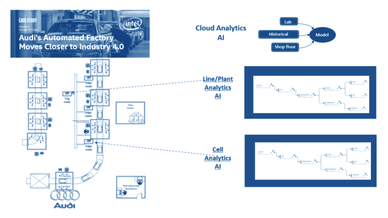
Figure 11: The mission critical edge: Tackling the challenges of fog computing and Industry 4.0
The mission critical edge has arrived. It is equipped to realize the original intent of Industry 4.0 and fog computing. It is not only tackling the challenges of the interface between embedded technology and information technology. It is harvesting the rich source of data promised by such a marriage, promising to make the gains demonstrated at Neckarsulm accessible to all.
I recently set up a demo to showcase how a customer can use subjects, also known as rooms, like containers. What I mean by that is that software...
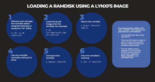
Based on several customers inquiries the purpose of this blog is to outline how to Allocate memory to a RAM disk Mount and unmount a RAM disk ...
_______________